 in the DMX stage view (if exactly one lamp is selected)
 DMX-Light) -> (
 DMX Stage viewt) in the DMX stage view (if exactly one lamp is selected)
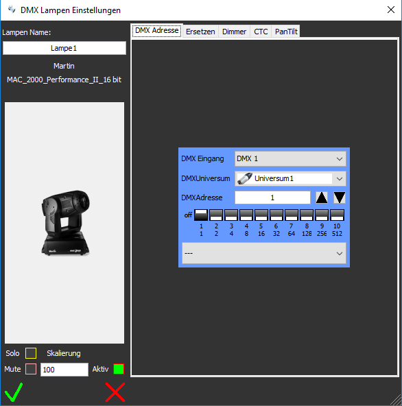
| Lamp Name | The name of the lamp can be assigned freely, it is used in the DMX stage view and is used to identify the lamp by the user. |
| Solo |
By clicking on the box with the yellow frame the solo function can be switched on and off. When
the solo function is switched on, all other lamps are muted internally
(see mute function), and only the lamps with the solo function switched
on transmit the values to the DMX universe. In other words, on the stage, only the lamps with the solo function switched on can be seen. If the solo function is activated, the box is filled with yellow color. The controller values are not affected by this, that is, you can store lighting presets and the controller values of the muted lamps are also stored. |
| Mute | By clicking on the box with the pink border the mute function can be switched on and off. When the mute function is activated, 0 values are sent to the DMX circuit. The deactivated channels are not affected by this (other than when the lamp is deactivated). If the mute function is activated, the box is filled pink. The controller values are not affected by this, that is, you can store lighting presets and the controller values of the muted lamps are also stored. |
| Scale | If a lamp has a dimmer
channel, the dimmer value can be increased or decreased in percent (0% -
200%) for the duration of a show. The desired value can be entered in the text field. If the value is set to 100 (%), the scale display becomes invisible in the stage view. The Scale function is useful when the show determines that a lamp is set too light or too dark. This function is not available for lamps that do not have a dimmer. The scale setting is not saved when saving the project. |
| Active | By clicking the box, a lamp can be deactivated or a deactivated lamp can be activated again. If the lamp is deactivated, the square is filled with red. If a lamp is deactivated, the value 0 is sent for all its channel values. Although you can still operate the mixer of the lamp, change its values and store them in light ambiences, these values are not transmitted to the lamp. This function is useful when e.g. On the stage a lamp was moved accidentally and this now blinds the audience or the lamp during the show a defect! |
| DMX Input | Most DMX lamps require less than 512 DMX channels and therefore only one DMXUniversum. There are also lamps, which use more than 512 channels and thus several DMX universes. Or a lamp is composed of several parts, each with its own DMX inputs. The lamp has accordingly several DMX inputs and thus for each input also a different starting address. Here you can select the lamp input. The number of inputs is determined by the lamp definition / lamp type. |
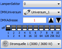
| DMXUniverse | Here, you assign the DMX input a DMXUniversum - see DMX Hardware Settings. |
| DMXAddress | Here you assign a DMX start address to the DMX input. If there are address conflicts with other lamps, this is shown with a red font, the entire setting area is then given a red frame. |
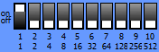 |
The start address is shown here as a DIP switches setting and can also be changed by clicking on a DIP switch. |
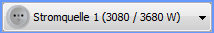 |
Here you can assign a current source to the lamp. The current sources can be defined in the DMX hardware settings. If too many lamps are connected to a current source (ie, if the maximum power of the lamps exceeds the power of the current source) this is displayed with a red frame. According to the name of the current source, their free watts / maximum watts are displayed. |
 |
Saves the settings |
 |
Cancels the settings, the old settings are retained. |
 |
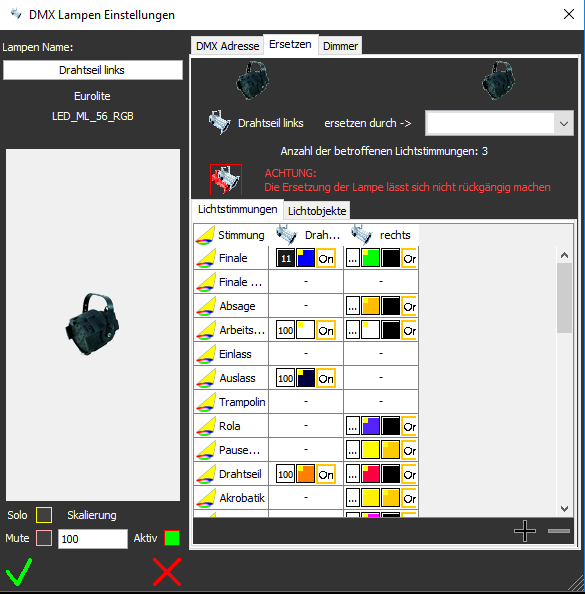
Here you can select a lamp to take over the tasks. |
 |
Here you can see the lamp track list for the lamp to be replaced and the selected lamp. The list is explained in more detail in Lamps Tracking. You can see where the lamp is used. A "-" is displayed in the track list when a lamp is not used. |
 This button replaces the lamp immediately Independent of saving or aborting. |
The replacement of the lamp is started here. The light ambiences and the object settings are copied to the new lamp, but only for lighting / objects in which the replacing lamp is not used by itself (dimmer channel = 0) |
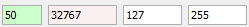 |
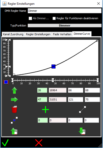
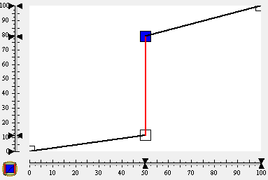
Set the y (output) value of a point The selected point is set to the set value on the Y axis The values are always the following: Percent, total = 256 * higherbyte + lowerbyte, higher byte, lower byte In the example below, you see the values for 50%. The higher byte value is always used for the properties of a lamp which only occupies one byte (DMX channel) To set the value, you can also click the Y ruler of the graphic NOTE: A point can not be set to a smaller value than the previous point |
 |
Fixes the points at their x-position If this is activated (button has a blue frame), you can no longer move the dots in x-direction. A new mouse click on this button deactivates the fixation |
|
Set the x (input) value of a point The selected point is set to the set value on the x axis. To set the value, you can also click the X ruler of the graphic ATTENTION: a point can not be pushed out beyond a neighboring point |
 |
Deletes the selected point |
 |
Adds a point at the set X position. The y value of the point is automatically set based on the existing curve. |
 |
Set the linear curve Clears all intermediate points from the curve and sets the first point to y position 0 and the last point to y position 100% |
 |
Add several points at regular intervals Adds multiple points with the set value as the distance |
| Set to the default values of the lamp type | Resets the curve as specified in the lamp definition |
 |
Opens a previously saved curve from a file |
 |
Saves the current curve to a file |
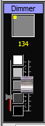 |
In addition to
the actual control knob, a controller display also has a narrow red bar
display, which indicates which value is sent to the lamp. In the case of a non-linear dimmer curve, the control knob is not necessarily at the same level as the red bar, since a corrected value is sent to the lamp. |
|
Saves the settings |
|
Cancels the settings |
 )
) .
.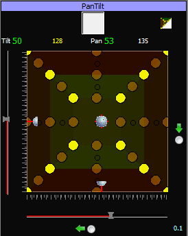
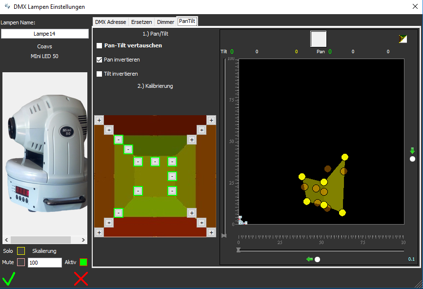
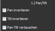
Step 1.) Switch
the lamp on using PanTilt, invert Pan, Tilt invert so that the lamp beam
moves on the stage according to the pan/tilt knob  That means: A) The light beam should move horizontally from left to right when you move the slider from left to right. B) The light beam should move from the bottom to the top when you move the knob from the bottom to the top. Note: If a moving head (not a scanner) is directly above / below a surface and the moving head is aligned parallel to the surface, this surface can not be calibrated - see step 2! |
 |
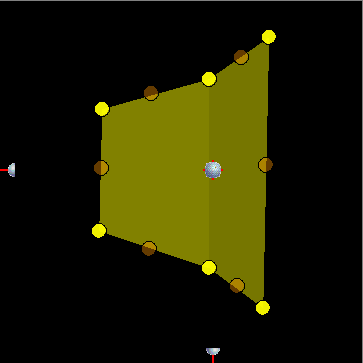
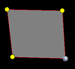
| Step 2.) Move the 4 corners of your stage area one after the other and save them with the corresponding (+) button. The angle difference (Pan or Tilt) between two points must not exceed 180 degrees. In practice, this means for movingheads: an area that is parallel under a moving head, you will not be able to calibrate because you would have to move the pan over 180 degrees to get to all 4 vertices. With scanners, however, this is quite possible. A remedy would be to install the movinghead at an angle to the surface. If you have set a point, the (+) button becomes a (-) button, which can be used to delete the point. |
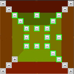 |
| Step 3.) Move to the center between 2 horizontal vertices of your stage area and save this position (+) The opposite center and the corresponding center of the adjoining surfaces are calculated automatically and can no longer be selected! |
|
| Step 4.) Move to the center between 2 vertical vertices of your stage surface and store this position (+) The opposite center and the corresponding center of the adjoining surfaces are calculated automatically and can no longer be selected! |
|
Saves the settings |
|
Cancels the settings |